
FOR PLC INTEGRATORS / CONTINUOUS ROPE MONITORING
Cable tension sensors. Match the PLC signal.
Check signal scaling, then define the rope sensor and controller interface together.
Published and reviewed November 1, 2026 · CTM Engineering
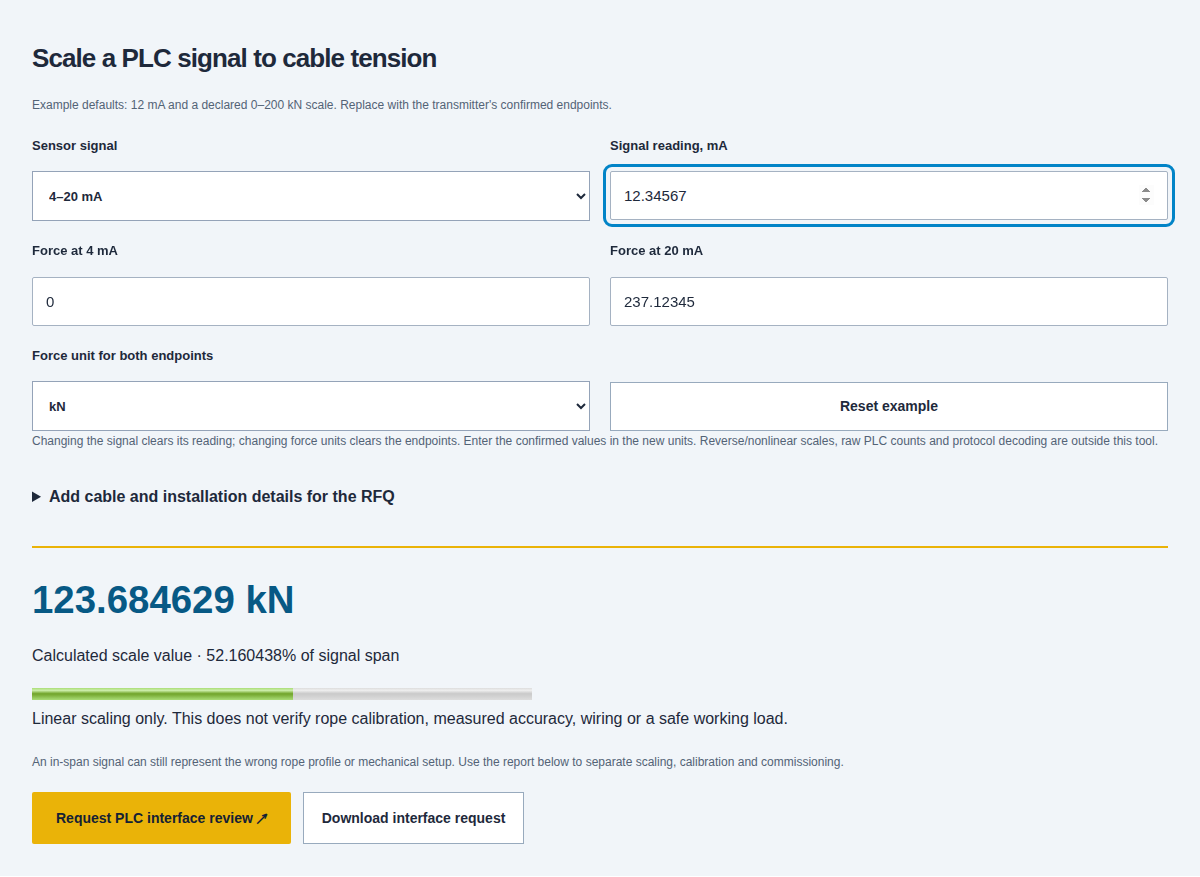
Scale a PLC signal to cable tension
Example defaults: 12 mA and a declared 0–200 kN scale. Replace with the transmitter's confirmed endpoints.
Linear scaling only. This does not verify rope calibration, measured accuracy, wiring or a safe working load.
An in-span signal can still represent the wrong rope profile or mechanical setup. Use the report below to separate scaling, calibration and commissioning.
Keep rope calibration and electrical scaling separate.
A cable tension sensor turns a defined mechanical input into an electrical signal. The PLC then interprets that signal. An accurate arithmetic conversion can still display the wrong force if the rope profile, installed geometry or transmitter configuration is wrong.
Agree three identities: the actual rope and contact arrangement, the delivered sensor/conditioner, and the receiver's configured scale. Keep their records together rather than correcting an unexplained error with a display offset.
Review CTM-FIX clamp and calibrated-range requests →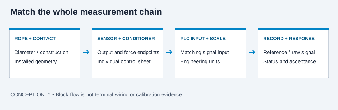
Start with the output actually supplied at the sensor cable.
The same mechanical sensing task can use different electronics. Match the delivered output to the input module before comparing a bare sensor price with a complete channel.
| Output path | Receiver to specify | Evidence needed before connection |
|---|---|---|
| Raw mV/V bridge | Matched strain-gauge input or conditioner with specified excitation | Bridge sensitivity, excitation, cable/sense arrangement and conditioner calibration; do not treat this as a 0–10 V transmitter. |
| Conditioned 4–20 mA | Compatible current input and correctly powered loop | Active/passive roles, two-/three-/four-wire topology, supply/load limits and force endpoints. |
| Conditioned 0–10 V | Compatible voltage input with the specified reference | Supply, common/reference connection, input impedance, isolation and scaled endpoints. |
| RS485 digital | Compatible physical port plus the actual protocol implementation | Protocol, device address, serial settings, register/data definition, units and timeout/status behavior. |
| Wireless sensor and receiver | Named receiver/gateway with the required onward output | The wireless link and PLC connection are separate selections; request the complete receiver-to-controller specification. |
Source scope: SENSY 5560S, PDF page 4, shows configuration-dependent electrical options; individual control sheet governs.
A stationary clamp and a moving-line sensor solve different problems.
The electrical interface does not decide how the sensor may contact the rope. Keep the operating mode and load path explicit in the request.
| Measurement task | Arrangement to review | What cannot be inferred |
|---|---|---|
| Continuous readings on a stationary cable section | CTM-FIX bolted clamp request with matched geometry and rope profile | A family diameter envelope does not approve every rope or usable low-load range. |
| Cable moving through the measuring assembly | CTM-RLT running-line request with sheaves, bend limits and speed scope | A fixed clamp is not a running guide; an analog output does not make it suitable for moving rope. |
| Portable readings on an accessible stationary span | CTM-QC meter request; agree logging or optional interface separately | A local display or Bluetooth report is not automatically a continuous PLC channel. |
| An in-line device or changed load path is proposed | Separate mechanical-system and installation review | The CTM clamp-on catalog does not establish an approved in-line component or an interchangeable load path. |
Source scope: SENSY 5560S fixed-cable scope, PDF page 2; CTM family references remain planning requests.
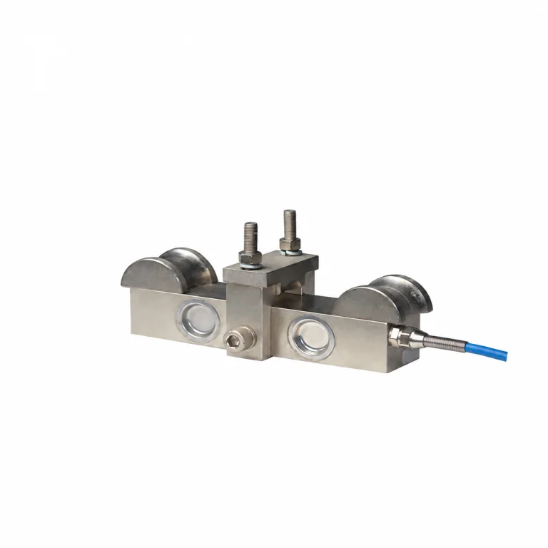
Read the output specification before choosing the PLC module.
A cable emerging from a clamp does not identify its output type. Ask for the supplied option code, terminal drawing, excitation/supply range and individual control sheet. The historical SENSY 5560S manual, page 4, demonstrates why the configuration matters.
For a CTM-FIX request, provide the input module and required output along with the rope. A quoted conditioned signal, raw bridge, remote receiver and relay controller are different line items.
Request the complete sensor-to-PLC scope →Specify the controller and terminal arrangement separately.
A controller enclosure is not a signal specification. Confirm the exact part number, supply, receiver, wiring drawing and protocol for the delivered configuration.
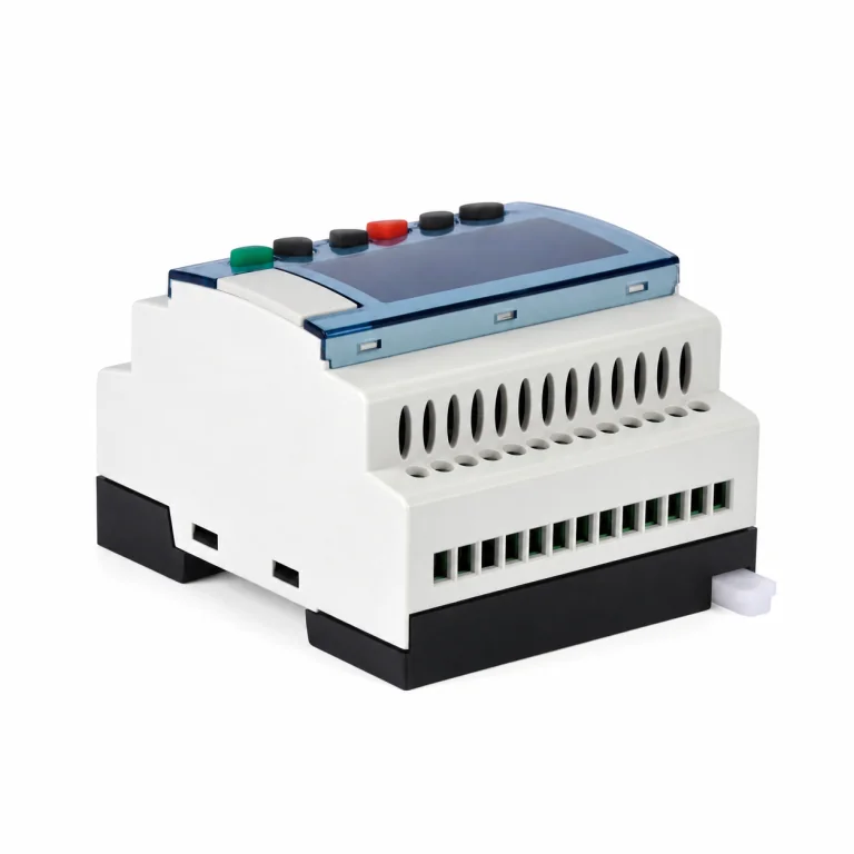
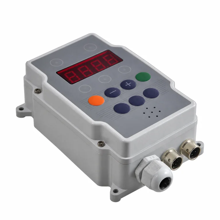
Supplier reference photographs. Exact model, rope fit, calibration and supplied accessories are agreed in the written offer.
Two endpoints define the linear signal-to-force map.
The worksheet uses F = F_low + (S − S_low) × (F_high − F_low) / (S_high − S_low). For 4–20 mA, S_low = 4 and S_high = 20. For 0–10 V they are 0 and 10. Force units must match both entered endpoints.
This is interpolation of a declared increasing linear scale. The actual transmitter characteristic must be confirmed before applying it. Rockwell's scaling explanation describes translating configured signal endpoints into engineering values. The worksheet rejects a reversed/zero force span and suppresses force outside the signal span instead of extrapolating.
Software input bound: absolute values up to 1,000,000,000. This is a numerical worksheet limit, not a CTM instrument range. Results are displayed to six decimal places; downloads preserve the original typed inputs and the calculated number. No physical accuracy is implied by the number of displayed digits.
Enter current in mA, not A. Confirm the actual signal endpoints even when a product name says “voltage output”: a 1–5 V or other offset signal cannot use this worksheet's exact 0–10 V mode. Use the supplied control sheet and a calculation matching those actual endpoints.
Compare the sensor, receiver and controller as one quoted channel.
Primary-source examples reviewed November 1, 2026. These are architecture differences, not drop-in cross-references, price comparisons or current availability promises.
| Named reference | Published architecture | Question for the written offer |
|---|---|---|
| SENSY 5560S | Fixed-cable sensor; its 2017 manual lists several electrical variants and refers to the individual control sheet. | Which exact output/option, control sheet, matched rope and terminal drawing are supplied? |
| Straightpoint BOLT | Kito Crosby identifies proprietary 2.4 GHz transmission to selected receivers. | Which receiver and onward PLC interface are included? Do not assume a current loop from the wireless description. |
| Gigasense CSM | A controller evaluating force-transmitter inputs and assigned system functions. | Which sensors, channel definitions and system validation are included? Its declared system attributes do not apply to another sensor. |
| CTM-FIX request | Rope-specific clamp and 4–20 mA / 0–10 V / RS485 interface requirements can be submitted. | Request a released drawing, confirmed electronics, calibrated force band and commissioning record; the request is not a verified product release. |
Vendor references: SENSY 5560S manual · Kito Crosby BOLT · Gigasense CSM. Read the individual configuration and document revision; no universal pinout is supplied here.
Keep out-of-span signals separate from normal tension values.
The worksheet checks a declared measuring span only. The integrator must use the actual equipment documentation for diagnostics and machine response.
| Observation | Interpretation boundary | Useful next check |
|---|---|---|
| 4 mA on a configured 4–20 mA channel | Corresponds to the declared lower engineering endpoint, which need not be zero force. | Compare the transmitter scale, PLC scale and reference record. |
| 0 mA on that current channel | Outside the normal measuring span; do not display it as zero cable tension. | Investigate power, wiring, receiver and documented diagnostic states before interpreting load. |
| 0 V on a 0–10 V channel | Can be a legitimate lower-end signal; the number alone does not distinguish every failure. | Review independent status/diagnostic provisions and the actual wiring. |
| Reading inside the expected span | Does not prove correct rope geometry, profile, zero reference or calibration. | Compare the installed mechanical setup and independent reference load. |
| Valid serial frames but implausible force | Communication success does not establish the correct data interpretation. | Check address convention, units, sign, scale, word order, freshness and status definition. |
Source scope: NI current-loop fundamentals; diagnostic interpretation remains device-specific.
RS485 needs a protocol and data map before it means tension.
Analog Devices AN-960 distinguishes RS485's electrical layer from the protocol used above it. A working physical connection does not identify which bytes represent force.
Include these serial-interface questions in the offer.
- Actual protocol and supported functions; device address, baud rate, parity and stop bits.
- Register/address convention, data type, sign, scale factor, engineering unit and byte/word order for multi-register values.
- Measured update rate versus PLC polling rate; timestamps or freshness indication where supplied.
- Status/diagnostic definitions, communications timeout and required response to missing or stale data.
- Approved terminal, shield/reference, termination, bias and isolation details for the actual equipment/network.
This is CTM's interface-review checklist, not an invented Modbus register map or wiring instruction. An RS485 request does not establish that a CTM configuration supports Modbus.
Request RS485 documentation ↗Separate electrical injection from a rope-load acceptance test.
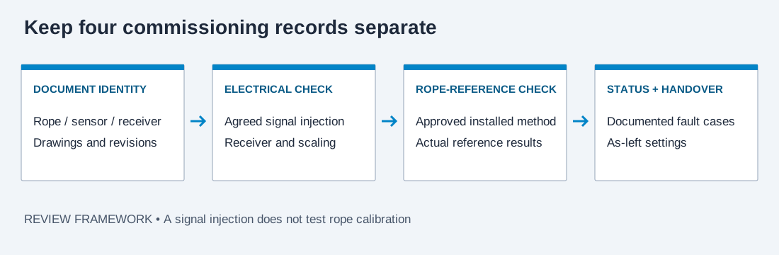
A repeatable commissioning record identifies what each check actually exercises. The following is a request/record framework, not an instruction to energize or load equipment.
| Check layer | Record | What it establishes / leaves open |
|---|---|---|
| Configuration review | Sensor, conditioner, PLC module, firmware/map, drawings and rope IDs | Confirms document identity; does not measure physical performance. |
| Electrical scaling check | Agreed injected signal points, receiver readings and engineering display | Exercises receiver/scaling logic; bypasses the rope sensor and its calibration. |
| Installed force-reference check | Approved load/reference method, rope profile, conditions and observed readings | Tests the defined installed chain over the agreed points; scope and uncertainty must be stated. |
| Status and alarm response | Documented simulated fault, delays, latch/reset and observed controller response | Validates the agreed test cases only; system acceptance remains with the responsible integrator. |
| Handover | As-left settings, records, revision, responsible person and service procedure | Makes future comparisons reproducible; retain the raw signal and interpreted value. |
Three software scenarios expose different integration questions.
Illustrative arithmetic only, using the stated inputs. These are not sensor measurements, calibration results or customer cases.
12 mA → 100 kN
Given 4–20 mA mapped to 0–200 kN, the midpoint produces 100 kN and 50% of span. A matching PLC display checks scaling arithmetic; it does not confirm the rope profile.
2.5 V → 35 lbf
Given 0–10 V mapped to 10–110 lbf, 25% of signal span produces 35 lbf. A nonzero lower force must be retained rather than silently replaced by zero.
3.5 mA → review signal
Given the same 4–20 mA span, the tool supplies no force. Confirm the signal/receiver and documented diagnostic state; no negative force, zero clamp or automatic alarm command is inferred.
Specify the documents and inclusions before comparing channel cost.
A low bare-sensor quote can omit the components or records that make a channel usable. Use this checklist for a like-for-like RFQ.
| Quotation line | State in your request | Confirm in the response |
|---|---|---|
| Mechanical and rope scope | Diameter, construction/material, normal/peak force, stationary/moving condition and clearance | Exact clamp/contact drawing, rope profile, usable force band and installation procedure. |
| Electronics and cable | Required output, PLC module, supply, run length and environmental conditions | Sensor/conditioner/receiver inclusion, terminal assignment, limits, cable/connector scope and protection evidence. |
| Calibration and records | Actual rope-profile list, force band, error definition and required documentation | Profile identity, load points, reference, results, uncertainty and acceptance criteria. |
| Commissioning and lifecycle | Required status behavior, logging, service access, quantity and destination | Test plan, documentation, recalibration/support terms and actual commercial delivery scope. |
Send the interface assumptions with the rope request.
The worksheet carries the chosen signal, exact typed endpoints and reading, rope identity and multiline notes into the shared RFQ. Add the required quantity, destination and actual project schedule there. You can also list up to 15 requested rope profiles for engineering review.
Build the PLC interface request ↗Cable sensor output and commissioning questions
Is a cable tension sensor the same as a handheld meter?
A sensor supplies a signal to a receiver or controller; a handheld meter is normally used for local checks. Some products combine functions, so identify the required operating mode, output and recording path in the offer.
Can a raw mV/V sensor connect to a normal voltage input?
Do not assume it can. Specify the bridge excitation and sensitivity and use a matched bridge input or conditioner. A raw bridge signal and a conditioned 0–10 V signal require different receiver arrangements.
Does 4 mA always mean zero cable tension?
No. It represents the lower endpoint assigned to that linear scale. If the confirmed lower force is 10 kN, the matching 4 mA display value is 10 kN. The worksheet lets you enter a nonzero lower endpoint.
Does the calculator create a rope calibration curve?
No. It interpolates between two declared electrical/engineering endpoints. It does not determine cable stiffness, contact deflection, calibrated accuracy, an approved rope profile or the physical load on your cable.
Why is there no force result below 4 mA?
This worksheet deliberately stops outside its declared measuring span. It does not extrapolate or replace a suspect value with zero. Follow the actual device diagnostic documentation before interpreting load.
Can zero volts be treated as a broken wire?
Not from the signal number alone on a 0–10 V scale. Zero volts may be a valid lower-end value. Agree separate status and fault-detection behavior for the actual equipment and installation.
Does an RS485 label guarantee Modbus RTU?
No. RS485 identifies an electrical interface. Request the actual protocol, serial settings and data map. If Modbus is offered, obtain its supported functions, addressing convention, data format, units and status behavior.
Can the tool convert PLC raw counts?
No. Enter a measured/configured current in mA or voltage in V. Raw-count endpoints and diagnostics depend on the input module and its selected range; use the module documentation before converting those counts.
Does BOLT wireless communication provide the PLC output I need?
The primary BOLT page describes selected wireless receivers. Specify the required onward controller interface and ask for the exact receiver/gateway configuration. A wireless link alone does not establish a direct 4–20 mA connection.
Does a correct displayed force prove overload protection?
No. A scaling calculation is one small part of a measurement chain. Mechanical limits, fault detection, control logic and the required system acceptance are separate matters for the responsible machine integrator.
Can I use the historical SENSY manual as CTM wiring instructions?
No. It illustrates how a named sensor can have configuration-dependent outputs. Use the released terminal drawing and individual control sheet for the actual supplied equipment; no SENSY wiring or ratings are transferred to CTM.
What should I send for a CTM-FIX interface quote?
Send exact rope identity and force needs, stationary mounting/access, requested signal, PLC module, supply, cable run, environment, status/alarm expectations, quantity and country. The worksheet preserves its typed inputs in the RFQ and text download.
Primary-source scope and the documents still needed
Sources reviewed November 1, 2026. Manufacturer documents govern their identified model/revision. CTM configuration-specific drawings, calibration results, electrical limits and acceptance records must be supplied with the actual offer.
- NI: current-loop components and receiver design
Updated February 3, 2025. Loop supply, receiver and voltage-drop considerations; not a CTM terminal drawing.
- Rockwell: signal-to-engineering-unit scaling
Two configured signal/engineering endpoints and linear interpolation; no rope calibration coefficients.
- Analog Devices AN-960: RS485 physical-layer scope
Distinguishes the electrical interface from higher-level protocols. The CTM register checklist is an engineering request, not an implemented protocol map.
- SENSY 5560S user manual
Revision August 21, 2017, PDF pages 2 and 4: fixed-cable contact geometry and configuration-specific output options/control sheet. Historical model document, not CTM wiring.
- Gigasense CSM controller overview
Named controller inputs and system functions. No Gigasense safety classification or protocol is transferred to CTM.
- Kito Crosby: Straightpoint BOLT
Current primary page identifies a wireless receiver path. Confirm the selected receiving interface; no CTM equivalence claim.